Selected Projects
Selected project experience demonstrating Stream3’s approach to brownfield modifications, specialized engineering analysis, facility upgrades, and construction-ready engineering for existing energy infrastructure.
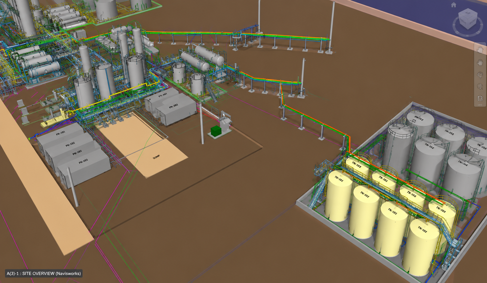
Central Processing Facility (CPF) — Brownfield Engineering Delaware Basin, New Mexico
Client Challenge
The operator required modifications to an existing crude oil storage tank battery and oil skimming system to address regulatory requirements associated with tank spacing and air-quality management. The work had to be implemented within an operating facility while minimizing disruption to ongoing production.
Engineering Approach
Working as part of the EPC project team, Stream3 provided brownfield piping engineering focused on constructability, regulatory requirements, and integration with existing facility conditions. Existing process conditions, layout constraints, tie-in locations, and demolition requirements were evaluated to develop a constructible modification strategy while minimizing disruption to operating systems.
Engineering Scope
- Existing-condition and facility layout review
- Tie-in and demolition definition
- Piping and Equipment Layout development
- VRU and flare-system integration
- Multi-discipline coordination with Process, Civil/Structural, and E&I
- Construction Engineering package development
- Field Engineering and Construction Support
- PVF material definition and procurement support
Facility Scope
- 8 crude oil storage tanks
- 2 transfer pumps
- Knockout vessel
- Vapor Recovery Unit (VRU)
- Blower
- Diaphragm pumps
- Low-pressure flare system
Key Deliverables
- Intelligent 3D Piping & Equipment model — AutoCAD Plant 3D
- Piping Plans and Fabrication Isometrics
- 3D schematic details
- Piping tie-in schedule
- Redlined P&IDs for demolition and tie-in definition
- Updated Plot Plan
- Pipe Support Layouts and Structural Steel Details
- PVF Bill of Materials generated from the intelligent 3D model
- Construction RFIs and Field Engineering Support
Project Outcome
The engineering package provided the EPC and operator with a coordinated, construction-ready solution for modifying the existing facility while maintaining operating continuity. The final design integrated piping modifications, equipment interfaces, tie-ins, supporting disciplines, and material requirements into a defined package for field execution.
HP Separator Blowdown System — Pipe Stress Analysis Gulf of Mexico, Texas
Client Challenge
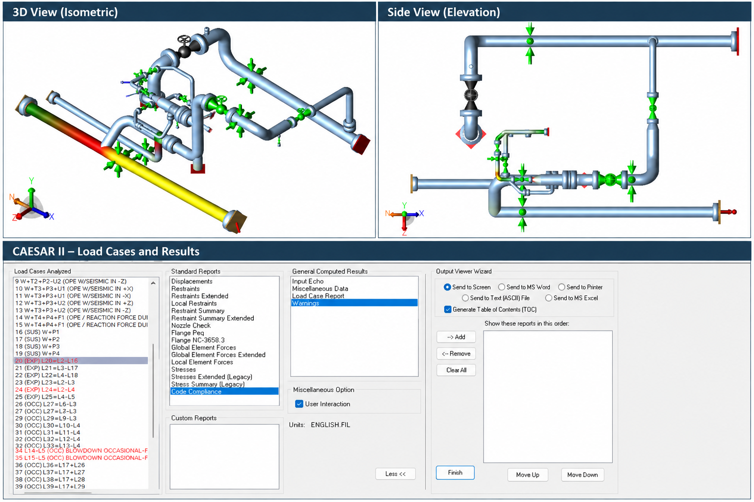
A Management of Change (MOC) for an existing HP separator blowdown system introduced modifications to the depressurization piping that required evaluation of the system response under operating and blowdown conditions. The assessment focused on the small-bore blowdown piping, where transient loading and piping flexibility could result in elevated bending stresses and support loads.
Engineering Approach
Stream3 provided pipe stress engineering support for the MOC by developing and evaluating the modified piping system in CAESAR II. The analysis considered static and dynamic loading associated with the blowdown event, with particular attention to piping flexibility, transient reaction loads, support behavior, and optimization of support locations and restraint types.
Engineering Scope
- Static & Dynamic Load Assessment
- Pipe Support Evaluation & Optimization
- Stress Isometric Markups
- Pipe Stress Report Development
Facility Scope
- HP Separator System/Natural Gas Offshore Platform
- Blowdown Valve (BDV) Branch
- Relief / Blowdown Header
Key Deliverables
- CAESAR II Native Model
- Stress Isometric Markups
- Pipe Stress Analysis Report
- Pipe Support Recommendations
Project Outcome
The analysis identified critical piping response associated with the blowdown event and supported optimization of pipe support locations and restraint types to improve piping behavior and maintain acceptable stress and load levels.
Salt Water Disposal Facility — Brownfield Engineering Delaware Basin, Texas
Client Challenge
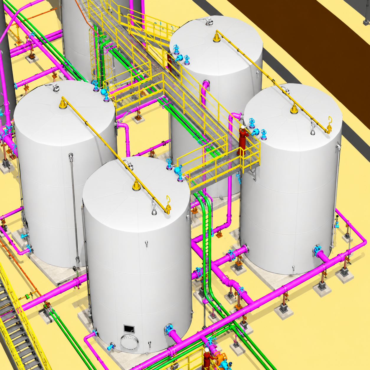
The client required restoration of an existing salt water disposal facility that had been out of operation for approximately five years. The facility was being prepared to handle approximately 22,500 BPD of produced water for injection into an authorized underground disposal reservoir. The engineering effort required evaluation of existing conditions, verification of piping tie-ins and pressure classes, and development of the modifications necessary to return the facility to service.
Engineering Approach
Stream3 reviewed existing process documentation and brownfield interfaces, verified tie-in pressure ratings, and developed the facility layout considering existing conditions, piping routing, containment, constructability, and multidisciplinary coordination. Pipe stress and equipment nozzle loads were also evaluated.
Engineering Scope
- Existing Process Documentation Review & Markups
- Existing Tie-In & Pressure Class Verification
- Equipment Location & Piping Layout Development
- Brownfield Piping Routing & Tie-In Design
- Secondary Containment Area Sizing & Layout
- Pipe Stress & Flexibility Verification
- Equipment Nozzle Load Qualification
- Multidisciplinary Engineering Coordination
Facility Scope
- 2 Gunbarrel Tanks
- 2 Basket Strainers
- 1 Oil Skim Tank
- 4 Produced Water Storage Tanks
- 1 Overflow Tank
- 2 SWD Charge Pumps
- 1 High-Pressure Injection Pumps
Key Deliverables
- Equipment Location Layout
- Intelligent 3D Piping & Equipment Model
- Piping Plans
- Fabrication Isometrics
- Bill of Materials (BOM)
- Pipe Stress Analysis Report
- Equipment Nozzle Load Qualification
Project Outcome
Engineering modifications supported the safe reactivation of the SWD facility and restoration of produced-water disposal capacity. Construction-ready engineering and direct field support provided the construction team with clear guidance for execution, helping reduce installation uncertainty, material purchasing errors, field rework, and associated schedule impacts. Engineering deliverables were reviewed and sealed by a licensed Professional Engineer (PE), providing the operator with professionally certified documentation for project execution.
Note: Project images are representative and provided for illustrative purposes only. They do not depict specific client facilities or disclose confidential client information.